Overview
Earlier editions of Umbra infractus used an Arduino Duemilanove as the main microcontroller. Because the Duemilanove has been discontinued, a new controller needed to be selected for future editions of the work. The replacement needed to be compact, reliable, and capable of controlling the artwork's two continuous-rotation servos with predictable timing.
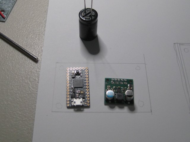
The Adafruit ItsyBitsy M0 Express was initially considered as a possible replacement because of its small size and sufficient processing capability. During development, two Hitec HSR-1425CR continuous-rotation servos were connected to the ItsyBitsy M0 Express. The servos were powered from a regulated 5.00 V supply and controlled through the Arduino Servo library using writeMicroseconds().
For a continuous-rotation servo, a pulse of approximately 1500 microseconds normally represents the neutral position. Values below or above neutral rotate the servo in opposite directions, with increasing distance from neutral corresponding approximately to increasing speed.
During initial testing, both servos stopped correctly at 1500 microseconds while the ItsyBitsy M0 was connected to a computer through USB. However, when the USB cable was removed and the board operated only from the artwork's battery supply, both servos slowly rotated instead of remaining stationary.
This unexpected behavior led to a closer investigation of the ItsyBitsy M0's timing, clock configuration, and suitability as a long-term replacement controller for future editions of Umbra infractus.
Initial Power Investigation
The first possibility considered was instability in the artwork's power supply. The system used four AA batteries feeding a 5 V / 3 A step-up/step-down regulator. The regulator supplied both the microcontroller and the two servos. A 4700 µF capacitor was installed across the servo power rail to reduce voltage drops caused by sudden servo current demand. The voltage between the ItsyBitsy's BAT and GND pins was measured while operating without USB and remained at approximately 5.00 V. The servo and microcontroller grounds were connected to a common ground point. These measurements made a simple under-voltage condition unlikely.
Finding the Battery-Only Neutral Position
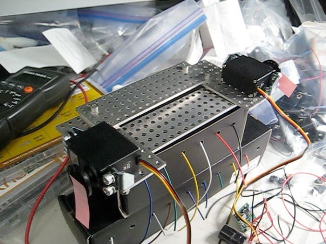
A neutral-finder program was created that allowed the servo pulse width to be changed in one-microsecond increments.When the ItsyBitsy M0 was connected through USB, both servos stopped at approximately:1500 µs. When the board was started using battery power alone, however, both servos rotated clockwise at 1500 µs. The pulse command had to be reduced considerably before the servos stopped. The neutral position was found at approximately:1458–1460 µs. A continuous-rotation servo may require a small individual neutral adjustment, but a difference of approximately 40 µs caused by whether USB was connected suggested that the problem was elsewhere in the system.
Another important observation occurred when USB was connected while the board was already running from battery power. At the battery-only neutral value of approximately 1458 µs, connecting USB caused the servos to begin rotating in the opposite direction. Disconnecting USB did not immediately restore the original behavior. After completely disconnecting and reconnecting the battery supply, the servos again stopped at the battery-only neutral value. This indicated that the operating state of the microcontroller's clock system was changing when USB became active.
Measuring the PWM Signal
Rather than continuing to adjust servo neutral values indirectly, the servo-control waveform was measured electrically.
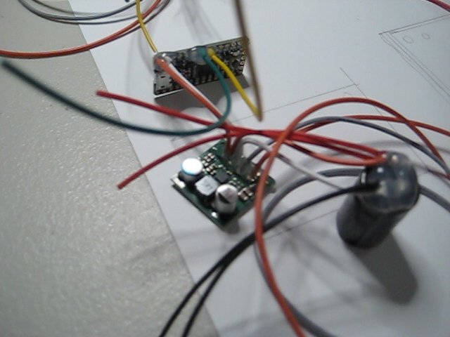
A Klein MM200 multimeter was connected between the servo signal pin and ground and used in frequency and duty-cycle measurement modes.
With the ItsyBitsy M0 running from battery power only, the servo signal measured approximately:
Frequency: 48.47–48.48 Hz
Duty cycle at a nominal 1500 µs command: approximately 7.4%
With USB connected, the frequency changed to approximately:
49.98 Hz
The expected servo refresh frequency was approximately 50 Hz, corresponding to a 20 ms period.
The difference between 48.47 Hz and 50 Hz is approximately 3%.
This measurement provided direct evidence that the timing generated by the microcontroller was different between battery-only and USB-connected operation.
Relationship Between Frequency Error and Servo Neutral
The measured frequency error closely corresponded to the neutral shift observed in the servos.
If a system expected to run at 50 Hz is actually running at approximately 48.47 Hz, its timing is roughly 3% slower than assumed.
A nominally requested 1500 µs pulse can therefore become significantly longer in real time if the software's timing calculations assume a faster clock than the hardware is actually using.
The battery-only servo neutral of approximately 1458–1460 µs was close to the amount of compensation expected from this measured clock difference.
This made a clock/timing issue a much stronger explanation than servo manufacturing tolerance alone.
How the SAMD21 Clock System Works
The ATSAMD21 used by the ItsyBitsy M0 is different from a traditional AVR Arduino such as the Uno.
The SAMD21 contains an internal Digital Frequency Locked Loop, called DFLL48M, that is used to generate a nominal 48 MHz system clock.
A frequency-locked loop does not inherently know that it is producing exactly 48 MHz. Its accuracy depends on how it is operated.
In open-loop operation, the DFLL runs using stored coarse and fine calibration values. Microchip specifies that the factory calibration value helps the DFLL produce a frequency close to 48 MHz, but the frequency is not continuously regulated against an external reference clock. In closed-loop operation, by contrast, the output frequency is continuously regulated against a reference clock, improving its accuracy and stability. Microchip, SAM D21/DA1 Family Data Sheet, DS40001882H, §17.6.7.1.1–17.6.7.1.2, p. 165 (PDF).
In closed-loop operation, the DFLL continuously regulates its output frequency against a reference clock. Once the multiplication factor is set, the oscillator's fine tuning is adjusted automatically so that the output remains aligned with the reference. This provides more predictable timing than open-loop operation. Microchip, SAM D21/DA1 Family Data Sheet, DS40001882H, §17.6.7.1.2, p. 165 (PDF).
USB Clock Recovery
The SAMD21 also provides a special USB clock-recovery mode.
USB sends a Start-of-Frame signal once every 1 ms. The SAMD21 can use this precise USB timing as the reference for the DFLL.
When USB Clock Recovery mode is active, the DFLL can generate the required 48 MHz USB clock using the USB Start-of-Frame (SOF) signal as its reference. Microchip specifies that the SOF signal is used as the DFLL reference clock, allowing crystal-less USB operation without requiring an external high-frequency crystal. Microchip, SAM D21/DA1 Family Data Sheet, DS40001882, §17.6.7.2.2, “USB Clock Recovery Mode” (PDF).
This behavior is consistent with the measurements observed during development:
Battery only:
approximately 48.47 Hz servo refresh
USB connected:
approximately 49.98 Hz servo refresh
The exact software configuration used by the Arduino/Adafruit core is more complicated than simply saying "USB always corrects the CPU clock," so the measurement itself was treated as the most important evidence. The board clearly behaved differently when USB became active, and the change was large enough to affect the neutral position of a continuous-rotation servo.
Why This Matters More for Continuous-Rotation Servos
A positional servo is generally commanded to move to an angle. A small pulse-width error might result in only a small positional error.
A continuous-rotation servo interprets the same signal differently.
Approximately:
1500 µs = stop
below neutral = rotation in one direction
above neutral = rotation in the opposite direction
The closer the command is to neutral, the slower the rotation.
This means a timing error of only a few microseconds may become visible as slow creeping.
A 40 µs error can therefore have a noticeable effect in this application.
Umbra infractus contains intentional periods of complete stillness, so a servo that slowly rotates during those pauses changes the behavior of the artwork rather than merely introducing a small mechanical tolerance.
3.3 V Logic Was Also Considered
The ItsyBitsy M0 uses 3.3 V logic while the HSR-1425CR servos are powered from 5 V.
One possible explanation considered during troubleshooting was that the 3.3 V signal level might be too close to the servo's input threshold, causing the servo to detect pulse edges differently.
A 5 V logic-level converter or a native 5 V microcontroller could therefore potentially improve signal margin.
However, the direct frequency measurement showed a clear timing difference between battery-only and USB operation.
The signal frequency changed from approximately 48.47 Hz to approximately 49.98 Hz.
Because this timing change directly corresponded with the servo-neutral change, clock accuracy became the primary explanation.
The 3.3 V logic level may still be less ideal than a 5 V signal for some servo inputs, but it did not explain the measured change in PWM frequency.
Option Considered: Software Compensation
One possible solution was to keep the ItsyBitsy M0 and compensate for the timing error in software.
Instead of treating 1500 as the neutral value, the final program could simply use approximately:
1458 µs
when running from battery power.
Another approach would be to calculate a correction factor from the measured frequency.
For example, if the expected frequency is 50 Hz but the measured frequency is 48.47 Hz, the program could scale requested servo pulse widths to compensate for the difference.
Conceptually:
corrected pulse = requested pulse × measured clock correction
corrected timer value
This could allow a command conceptually representing 1500 µs to generate a pulse much closer to 1500 µs in real time.
Why Software Compensation Was Not Chosen
Although software compensation appeared feasible, it introduced several concerns for a permanent or editioned artwork.
First, the correction may be specific to an individual board.
The SAMD21's internal DFLL calibration varies from device to device. A second ItsyBitsy M0 might not produce exactly the same battery-only clock frequency as the first one.
This could mean that each edition would require individual measurement and calibration.
For example:
Edition 1 correction: 0.969
Edition 2 correction: 0.972
Edition 3 correction: 0.967
This would make controller replacement and long-term conservation more complicated.
Temperature Stability
A second concern was temperature.
An internally generated oscillator that is not continuously locked to an external frequency reference can change slightly with temperature, supply conditions, and semiconductor variation.
Microchip distinguishes clearly between open-loop DFLL operation and closed-loop operation using a reference clock. In open-loop mode, the DFLL output frequency is determined by the programmed coarse and fine calibration values rather than being continuously corrected against a reference clock. In closed-loop operation, by contrast, the output frequency is continuously regulated against a reference clock. Microchip, SAM D21/DA1 Family Data Sheet, DS40001882H, §17.6.7.1.1–17.6.7.1.2, p. 165 (PDF).
For many microcontroller applications, a small amount of clock variation is irrelevant.
For a continuous-rotation servo near neutral, however, even a small percentage matters.
For a nominal 1500 µs pulse:
0.1% timing change = approximately 1.5 µs
0.5% timing change = approximately 7.5 µs
1% timing change = approximately 15 µs
3% timing change = approximately 45 µs
A few microseconds may be enough to produce visible slow movement in a sensitive continuous-rotation servo.
This made a one-time room-temperature calibration less attractive for an artwork that may be installed for years in different galleries, storage environments, or collections.
Long-Term Maintenance and Editions
The artwork is intended not only as a single prototype but as a potentially editioned work.
For an editioned artwork, hardware replacement should ideally be straightforward.
If an ItsyBitsy M0 failed several years later and a replacement board were installed, the new board might require a new frequency measurement and new compensation constant.
The firmware would therefore not necessarily be fully interchangeable between editions.
That was considered undesirable from a conservation and maintenance standpoint.
A simpler controller architecture where a replacement board can receive the same firmware and behave predictably is preferable.
Option Considered: Direct SAMD21 Hardware PWM
Another option was to bypass the Arduino Servo library and configure the SAMD21 timer peripherals directly.
This approach would allow explicit control of:
timer clock source
prescaler
PWM period
compare register
servo pulse width
The intention was to generate a 50 Hz signal directly in hardware rather than relying on the abstraction provided by Servo.h.
Initial experiments confirmed that hardware PWM generation was possible.
However, the SAMD21 has multiple timer peripherals, including TCC and TC units, and individual ItsyBitsy pins map to different timer channels.
D9 and D10, for example, did not behave as a simple pair on one shared timer configuration.
Several experiments showed that direct-register configuration required careful verification of the ItsyBitsy M0's exact pin multiplexing and clock routing.
This approach remained technically possible, but it increased firmware complexity considerably.
Why Custom Hardware PWM Was Not Used for the Exhibition Version
The artwork was being prepared for a gallery opening within a few days.
A custom SAMD21 timer implementation would have required additional testing of:
servo neutral
frequency accuracy
USB connection and disconnection
battery-only startup
power cycling
temperature stability
timer channel mapping
interaction with future sensors or radio communication
Because the simpler Arduino Uno configuration had already demonstrated stable servo neutral behavior, continuing to develop a custom timer solution immediately before the exhibition was considered unnecessary risk.
Difference Between the ItsyBitsy M0 and Boards With an External Clock Reference
An important distinction is that not all SAMD21 boards use exactly the same clock hardware.
The Feather M0 Express uses the same ATSAMD21G18 processor as the ItsyBitsy M0 Express, but Adafruit explicitly specifies a 32.768 kHz crystal for clock generation and RTC on the Feather M0 Express. Adafruit Learning System
A low-frequency crystal can act as an accurate reference for the SAMD21 DFLL.
The relationship is conceptually:
32.768 kHz crystal
↓
DFLL reference
↓
48 MHz system clock
The DFLL continually adjusts its output relative to the external crystal reference.
This is fundamentally different from running the 48 MHz DFLL without an equally accurate external reference.
A crystal is a physical resonant component whose oscillation frequency is controlled by the mechanical properties of quartz. Its frequency stability is generally far better than that of an unreferenced internal RC or digitally calibrated oscillator.
The ItsyBitsy M0 product specifications list the SAMD21 running at 48 MHz but do not list the 32.768 kHz crystal that Adafruit explicitly lists for the Feather M0 Express. Adafruit
This makes the Feather M0 a more appropriate SAMD21 platform when accurate standalone timing is important.
Comparison With the Arduino Uno
The Arduino Uno uses a different architecture.
Its ATmega328P runs at 16 MHz from an external ceramic resonator. Arduino specifies a 16 MHz ceramic resonator as the processor's clock source. Arduino Documentation
A ceramic resonator is generally less precise than a quartz crystal, but it is still a dedicated external frequency reference rather than a free-running internal oscillator.
The Uno therefore has a relatively simple timing model:
external 16 MHz resonator
↓
ATmega328P timer
↓
Servo library
↓
servo pulse
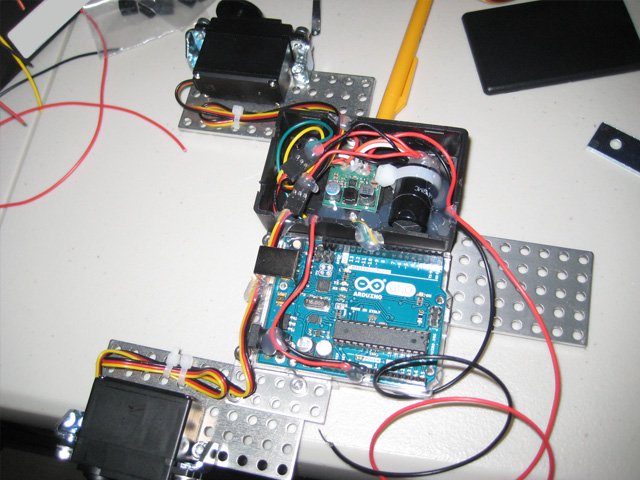
During testing, the Uno generated a neutral servo command that consistently stopped both HSR-1425CR servos at approximately 1500 µs.
This made it the safest controller for the immediate exhibition build.
Comparison With the SparkFun Pro Mini
The SparkFun Arduino Pro Mini 5V / 16 MHz uses the same ATmega328-class architecture and is designed as a compact embedded alternative to the Uno.
SparkFun specifies an external 16 MHz resonator with approximately 0.5% tolerance. SparkFun Electronics
This provides a small physical footprint while retaining the familiar AVR timing behavior.
The Pro Mini was considered a good compact alternative, although the Uno was selected for the exhibition because it had already been tested in the actual artwork.
Future Controller: ItsyBitsy 32u4 5V
For future versions of Umbra infractus, the planned controller is the Adafruit ItsyBitsy 32u4 5V / 16 MHz.
It uses an ATmega32u4 running at 5 V and 16 MHz and is physically almost the same size as the ItsyBitsy M0. Adafruit describes it as providing much of the capability of an Arduino Uno while operating at the same speed and voltage class as an Uno or Leonardo. Adafruit
The board also uses a dedicated external 16 MHz ceramic resonator as the clock source for the ATmega32u4. This differs from the standalone clock behavior encountered with the ItsyBitsy M0, where the SAMD21's 48 MHz DFLL was operating without the same kind of fixed external frequency reference. Although a ceramic resonator is generally less precise than a quartz crystal, it provides a stable external timing reference and is well suited to the timing requirements of this artwork. Adafruit, ItsyBitsy 32u4 5V schematic
For Umbra infractus, its advantages include:
small physical size
external 16 MHz resonator clock
native 5 V logic
mature AVR Arduino environment
adequate processing power for two servos and random behavioral logic
onboard USB programming
no need for the computational resources of the SAMD21
The 32u4 is considerably less powerful than the SAMD21 in RAM, flash, and processing speed, but those resources are unnecessary for this particular artwork.
Exhibition Solution
For the exhibition version (2026 September) of Umbra infractus, the controller was changed to an Arduino Uno.
The configuration was:
Servo 1 signal: D9
Servo 2 signal: D10
Servo power: regulated 5.00 V
Controller power: regulated 5.00 V
All grounds: common
Servo neutral: 1500 µs
A 4700 µF capacitor was connected across the servo power rail.
The servos were controlled using the standard Arduino Servo library and writeMicroseconds().
Conclusion
The investigation did not show that the ItsyBitsy M0 Express was generally unreliable.
Instead, it revealed that its standalone timing architecture was not ideal for this particular use of continuous-rotation servos.
The key observation was not simply that the servo neutral value changed, but that the control waveform itself changed measurably:
Battery-only operation:
approximately 48.47–48.48 Hz
USB-connected operation:
approximately 49.98 Hz
That measurement connected the mechanical symptom directly to a timing difference.
Several solutions were considered:
adjusting neutral values in software
applying a clock correction factor
calibrating each board individually
adding logic-level conversion
using direct SAMD21 hardware timers
moving to another SAMD21 board with an external reference crystal
using a 5 V AVR-based controller
The immediate exhibition version therefore used an Arduino Uno, while the compact ItsyBitsy 32u4 5V was selected as the preferred direction for future editions.
The debugging process also demonstrated a broader principle for kinetic artwork electronics: when behavior depends on very small timing differences, software values such as "1500 microseconds" should not automatically be assumed to represent the same physical signal on every microcontroller platform. Measuring the actual electrical waveform can reveal differences that are otherwise difficult to distinguish from mechanical or power-related problems.
 Wonbin's YouTube Channel